MCU Overview
General Overview
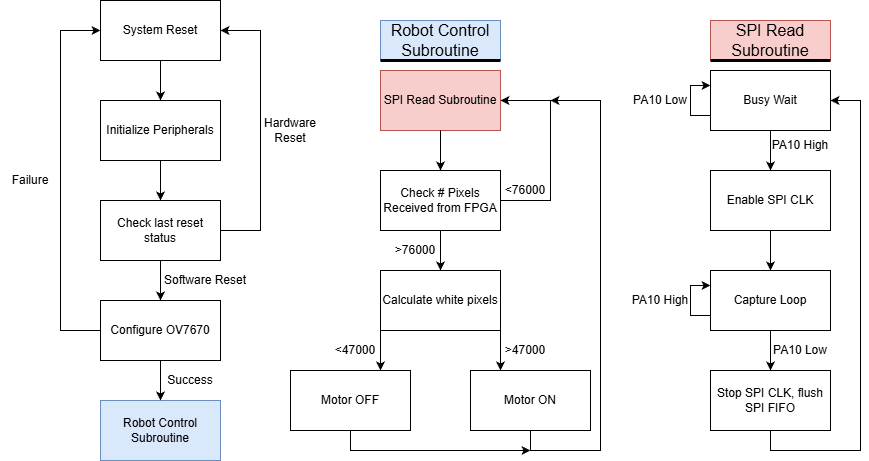
The project uses two MCUs, each of which is independent from the other. The MCUs purpose is to read bit-masked pixel data from an FPGA over SPI in frame packets, determine the number of black pixels in the frame, and control a motor based on that number. Each MCU also handles the configuration of an OV7670 camera over I2C. A diagram depicting the subroutines on the MCU can be seen below.
OV7670 Configuration
The OV7670 Camera module supports register reads and writes over a communication protocol called SCCB, which is very similar to I2C except it doesn’t support multi-byte transmission & sends a don’t care (X) instead of an ACK/NACK at the end of each transmission. By adding pull-up resistors and limiting ourselves to single-byte transmissions, we were able to use the I2C peripheral on the MCU to configure registers on the OV7670, which was very convenient. We were then able to configure the OV7670 in QVGA YUV mode, giving us a resolution of 320x240 pixels.
The biggest sticking point with the camera was configuring it to have deterministic behavior. For a long time, we were disabling autoexposure, but the camera still wasn’t acting deterministically. The key is to disable autoexposure first, the enable exposure setting by setting specific registers, which can be found in the OV7670 datasheet & implementation guide. We unfortunately discovered this 24 hours before checkoff, which resulted in us having to change our plan for our control system.
Robot Control
The plan was to scan the bit-masked frame to find the black line’s left and right edges, take their midpoint, and use this to compute the line’s horizontal position error relative to the image center. To get the line angle, the MCU would compare midpoints of every row and compute the slope/angle of the line segment connecting them. However, the aforementioned delays in configuring the OV7670 meant that this plan had to be scrapped. We decided to transition to a control system akin to what’s used in line-following robots that use two IR sensors to detect a line. This required the use of two boards, one to control a camera and motor on each side. The robot is then controlled by having each MCU read a frame from the FPGA, compare the number of black pixels to a predefined threshold, and then having it drive its motor depending on the threshold.
We know that the MCU receives full frames from the FPGA (within some tolerance), because the control loop includes a condition that the MCU doesn’t control the motor it’s connected to unless it receives at least 76000 pixels from the FPGA. This is actually a critical function for robot control, as if we controlled off partial frames, the robot wouldn’t work.
MCU Peripherals & HAL Usage
The Hardware Abstraction Layer (HAL) provided by STM was used by the team during this project, in order to gain experience with it. Use of the HAL enables a much simpler initialization of the STM32L432KC’s peripherals than using CMSIS templates, as it eliminates the need to write our own drivers, instead enabling the use of vendor-provided peripheral drivers. The peripherals used by the team, as well as their usage, are briefly described below.
- TIM1
- TIM1 was used to generate the XCLK for the OV7670 camera module. The XCLK was configured to a frequency of 10MHz by dividing the system clock, which was set at 80MHz
- I2C1
- The I2C1 peripheral was used to enable configuration of the OV7670’s registers over the SCCB bus.
- SPI1
- The SPI1 peripheral was used to enable fast data capture of bit-masked pixel data from the FPGA. Although the FPGA did not have SPI configured, the nature of the data transfer protocol between the MCU and FPGA meant that the SPI peripheral on the MCU improved data transfer rate compared to a naive polling-based approach.
- LPTIM2
- The team discovered the LPTIM2 peripheral when trying to enable PWM motor control without moving the XCLK line off of PA10. When evaluating the available pins on the MCU that were connected to the breakout board, the team discovered that PA8 could be configured as a PWM signal using AF14, which enables the low-power timer peripheral on the MCU. This was a fun discovery, as we wouldn’t have ran into this peripheral otherwise.