Project Proposal
Project Design & Overview
The inspiration for this project came from a project Diego completed in a robotics class during his junior year of high school. He built an extremely rudimentary line-follower robot using an Arduino and two IR sensors. The goal of this project is to once again build a line-follower robot, this time interfacing an OV7670 camera with an UPduino iCE40 UP5K FPGA board (“the FPGA”) and a STM32L432KC microcontroller (“the MCU”). The FPGA will interface with the OV7670 to detect the line and send the resultant information to the MCU for robot control.
Specifications
- Robot follows a black line on white paper
- Robot doesn’t move if no line is detected
- Robot uses camera as vision interface
- FPGA receives pixel data from OV7670
- FPGA sends masked pixel data to MCU over a communication interface
- MCU configures registers on OV7670 over SCCB/I2C interface
- MCU is able to receive full frames from FPGA
Design Details
MCU Design & New Functionality
The MCU will have four critical functions. It needs to configure the OV7670 over the SCCB interface, send the FPGA a signal to drive XCLK, read bit-masked frames from the FPGA over SPI, and control the position of the robot along the line based on the data from the frames. The new functionality on the MCU will be the SCCB peripheral and the implementation of DMA to enable high-speed SPI reads.
FPGA Design & New Functionality
The FPGA has several critical functions, notably to: drive XCLK at 24MHz, read & process pixel data from the OV7670, and communicate that data to the MCU over SPI. In order to send pixel data to the MCU, a double SPRAM buffer will be implemented. The new functionality on the FPGA will be the SPRAM buffer and SPI communication.
New Hardware
The main piece of new hardware being integrated is the OV7670 camera module.
Riskiest Element
Using the MCU to configure the OV7670 is definitely the riskiest element of the project. Although the SCCB interface is based on I2C, literature review indicated that the I2C interface on the MCU would not be able to configure the camera. So, the team will need to bit-bang an SCCB interface. The team will attempt to mitigate risk by consulting examples available online.
Technical Documentation
Block Diagram
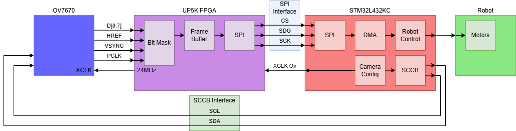
The block diagram in Figure 1 provides a general outline of the protocols and interfaces that will be utilized in the project.
Performance Calculations
SPI Performance
According to the datasheet of the STM32, the maximum frequency of SCK when configured in master/receiver full-duplex mode is 40MHz when VDD ∈ [2.7, 3.6]. A 40 MHz SCK results in a maximum throughput of approximately 5 MB/s. Since each frame will be 9.6kB, each frame can be read in approximately 1.92ms. For a frame rate of 30 fps, the FPGA will produce a frame every 33.3ms. This means that there will be approximately 31.3 ms for robot control.
LUT Usage
These are meant to be preliminary order-of-magnitude calculations. The FPGA used (Lattice iCE40 UP5K) has hardware SPI support, so the SPI interface requires no LUTs.
- Assuming 8 8-bit counters for things like write address, read address, frame ID, etc, we have 64 LUTs
- For bit masking, a comparator can be used. If we compare on all 8 bits of the Y (using a YUV pixel format), we’d need 8 LUTs
- To encode the double buffer, we’d need enough LUTs for state. If we assume 20 states (massive overestimate), we’d at most 100 LUTs.
- To account for any other random parts of the design, we’ll add in 200 extra LUTs
This only brings us <400 LUTs. Although we likely missed aspects of the design, it is exceedingly unlikely that we come close to even 40% LUT resource usage on the FPGA, as the FPGA has ~5000 LUTs available
SPRAM Buffer Sizing
According to the datasheet for the FPGA, we have 1 MB of SPRAM available. A 1-bit mask of a QVGA image only requires 9.6kB of space. So, we have more than enough space in SPRAM.
Project Management
Bill of Materials
| Item | Part Number | Quantity | Price | Source |
|---|---|---|---|---|
| Camera Module | OV7670 | 1 | $8-12 (+ shipping) | Amazon |
| Potentiometer (Threshold control) | 10 k \(\Omega\) Linear Pot | 1 | Stockroom | Stockroom |
| DC Motors | TT Gear Motor (3-6 V) | 2 | Stockroom | Stockroom |
| Motor Driver | L298N | 1 | $3-6 | Amazon/Stockroom |
| Robot Chassis Kit | N/A | 1 | Stockroom | Stockroom |
Project Timeline
| Task(s) | Date |
|---|---|
| Finish proposal | 10/20/25 |
| Start Project | 10/21/25 |
| Prepare slides for design review | 11/7/25 |
| Finish Midpoint Report & Demo | 11/16/25 |
| Final Checkoff | 12/5/25 |
| Final Report Due | 12/7/25 |
| Demo Day | 12/8/25 |
Task Delegation
| Diego | Aabhas |
|---|---|
| Start MCU Code | Start FPGA Code |
| Check FPGA Code | Check MCU Code |
| Decide MCU task scheduling | Decide MCU task scheduling |
| Write robot control code | Check robot control code |
| Check robot | Assemble robot |
| Write verification | Write verification |
| Write documentation | Write documentation |
Our aim is to work together as much as possible, so that both team members are full owners of the project.