Project Midpoint Report
Progress Report
Overall Progress
As of the midpoint report being written, the team has accomplished the following: - Configuration of the OV7670 camera module through register writes from the MCU over an I2C interface - Pixel data capture from the OV7670 camera module on the FPGA - Streaming bit-masked pixel data from the FPGA to the MCU over a 1-directional parallel bus - Full bit-masked frame capture and display on the MCU using GPIO polling
As a reminder, the overall specs for the project are listed below, with the already-completed specs checked off.
At this point in the project, the team believes that the riskiest elements have been completed, as the camera is now able to be configured, and camera data is captured by the FPGA, analyzed, and sent to the MCU.
Riskiest Element
Prior to beginning work on the project, the team identified the riskiest element as configuring the OV7670 CMOS camera using the MCU over the SCCB interface. This was because there weren’t many examples on how to implement this interface, which created the possibility of the team needing to bit-bang our own SCCB interface, which is similar to I2C but has some quite relevant differences, the main one being that the SCCB controller on the OV7670 sends a “don’t care” bit as the 9th bit, while the I2C interface on the MCU expects an “ACK” bit to be sent from the OV7670 to acknowledge data. However, the team was succesfully able to configure the OV7670 using the I2C peripheral on the MCU.
Summary of Remaining Work
Now that the team is receiving full frames on the MCU, the remaining work can be broken into three phases.
Phase 1: Finalizing FPGA & MCU Code
Currently, the FPGA sends the MCU a pixel as soon as it finishes bit-masking it. For the final design, the goal will be to implement an asynchronous FIFO using the SPRAM on the MCU, so that full frames can be read much quicker, leaving time for robot control.
Phase 2: Mechanical Design
Although the team has purchased a robot kit, some design considerations need to be taken into account, as the camera needs to be mounted on the robot along with the rest of the parts. The camera module will likely need a light mounted near it to illuminate the track, which would also require the integration of a lens hood.
Phase 3: System Integration & Testing
Once the peripherals are fully integrated and mounted on the robot chassis, the team expects that there will be significant work left to do on tuning the control system on the MCU, as well as tuning camera exposure settings to improve line recognition. Also, the field of view of the camera will need to be determined, and the camera will potentially need to be focused.
Documentation
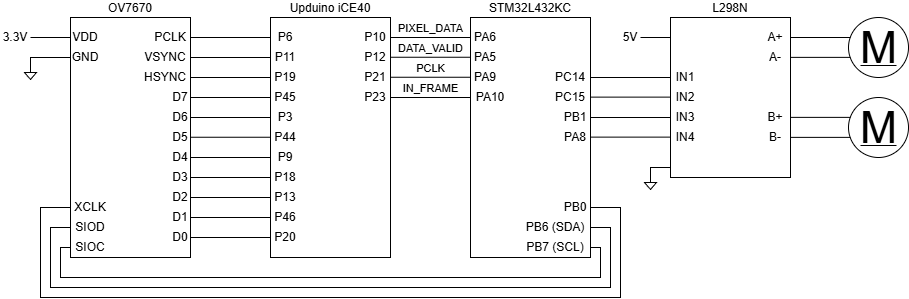
Schematic
The team has created a semi-finalized schematic representing all the connections between the different peripherals in the system, which can be seen below.
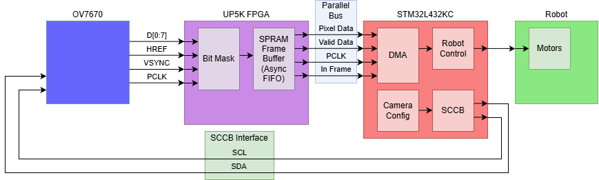
Block Diagram
The block diagram has been updated slightly since the proposal to reflect some of the changes in the design methodology.
MCU Routine Overview
Currently, the MCU uses a super loop and polling to capture frame data. Eventually, the hope is to use FreeRTOS, although that is not a spec for the project because it’s a stretch goal. The current routine involves waiting for the frame-active pin to go high, then reading pixel data on the falling edge of PCLK when the pixel data is valid. The pixel data is currently stored in RAM on the MCU, as each frame is only 9.6kB, so one frame can be stored in RAM at a time. Once the asynchronous FIFO has been implemented on the FPGA, the entire frame will be streamed to the MCU, so the MCU will not need to check whether the data is valid. When combined with DMA for frame capture, this will allow for much faster frame reads and will decrease the amount of dropped frames.