Project Final Checkoff Report
deliverables
Project Final Checkoff Report
One Pager
As a reminder, the overall specs for the project are listed below. All specs were completed!
-
- This spec essentially encapsulates the project, and was confirmed through visual observation of the final robot.
-
- This spec was confirmed by observing the performance of the robot.
-
- The only sensors being used to control the robot are cameras. Due to difficulties encountered with camera noise, two cameras are used to control the robot, with control determined by the amount of black pixels in each image.
-
- The FPGA receiving pixel data from the OV7670 was confirmed through the performance of our system. It was difficult to verify the design worked in the real world until we had our MCU configured to receive data from the FPGA, but once we did, we were able to confirm that the MCU received changing pixel data from the FPGA, which told us that the FPGA was receiving pixel data from the OV7670. Otherwise, we wouldn’t be able to see the difference between black and white!
-
- The FPGA sends frames to the MCU over a modified SPI bus, where the MCU is configured as the master. Because the communication between the FPGA and MCU is one-directional, only the COPI and CLK lines were connected. The MCU recevies a signal from the FPGA indicating that a frame is ready to be sent. Once it receives that signal, it sends the SPI CLK to the FPGA, and the FPGA shifts data out over that clock.
-
- We were able to confirm that the MCU configures registers on the OV7670 early on in the project. SCCB effectively acts as I2C, but is named differently for licensing reasons. Using the MCU’s I2C peripheral, we were able to write to specific registers and then read back those registers to confirm succesful writes.
-
- We know that the MCU receives full frames from the FPGA (within some tolerance), because the control loop includes a condition that the MCU doesn’t control the motor it’s connected to unless it receives at least 76000 pixels from the FPGA. This is actually a critical function for robot control, as if we controlled off partial frames, the robot’s performance would likely suffer.
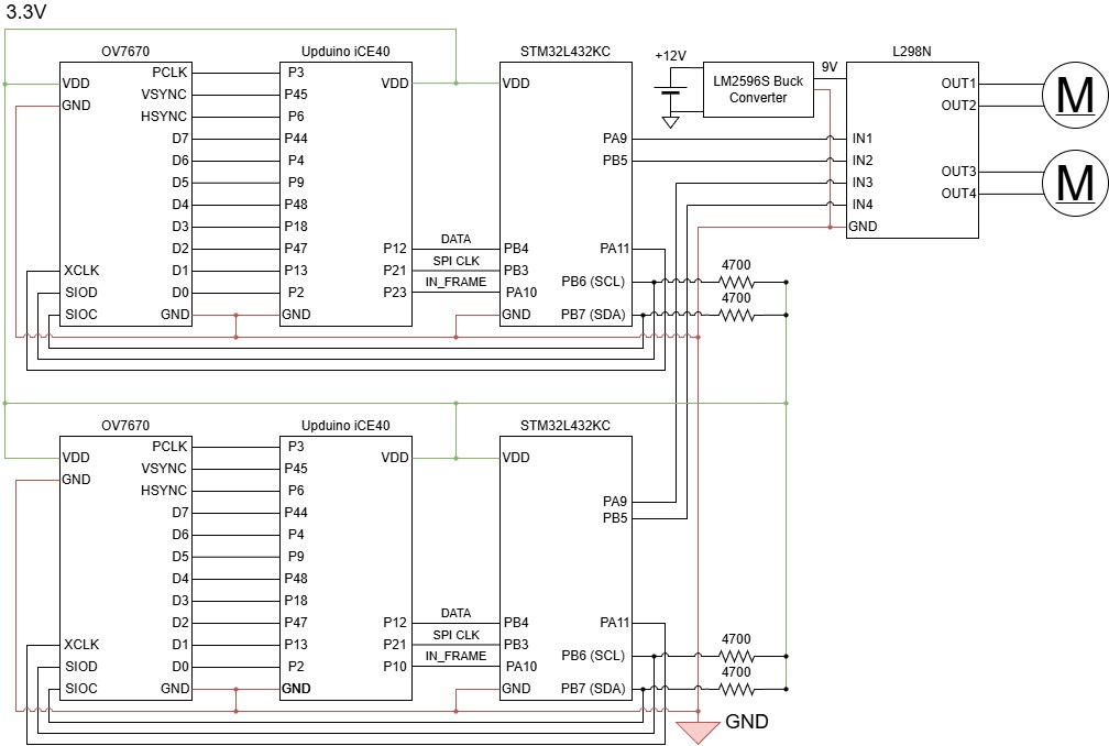
Schematic
The final system schematic representing all the connections between the different peripherals in the system can be seen below.
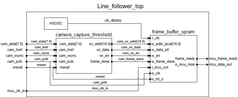
Block Diagram
The team produced a block diagram describing our RTL, which can be seen below.
Code
The source code for the final project can be found in the team’s Github repository